Adapting ENG Lenses to DSLR Production, Part 2: Power & Rigging
Adapting servo zoom ENG lenses to your DSLR rig with suitable rails and power makes for a smooth transition from prosumer camcorder to large-sensor video camera.
In the first part of this series, I considered the usefulness of putting a servo zoom, broadcast ENG lens on a DSLR used to shoot video. I wrote about the many types of ENG lenses out there and honed the selection down to a B4 mount, 2/3" ENG lens as the most useful. Although I used my Panasonic GH2 to test the lenses, this research lends itself to any DSLR with crop modes on the sensor, or for any lens with a built-in 2x "doubler."
The goal of adding an ENG (electronic news gathering) lens onto a DSLR is primarily to take advantage of the servo zoom part--the smooth, consistent, motorized zoom. But there are other useful advantages, even if you never use the powered servo zoom. You have multiple focal lengths like any zoom lens and a consistently low f-stop throughout the zoom range. A third, less-talked-about advantage is the cost-effectiveness. For the cost of two good, bright, prime lenses, you can get a decent HD camcorder lens for your camera. So let's talk more about getting that ENG lens up and running.
Power
After Part 1 of my ENG lens series ran, I received a lot of feedback--even phone calls. The main question readers had was, "How do you power the lens?" It turns out the short answer is actually very simple: 12v DC.
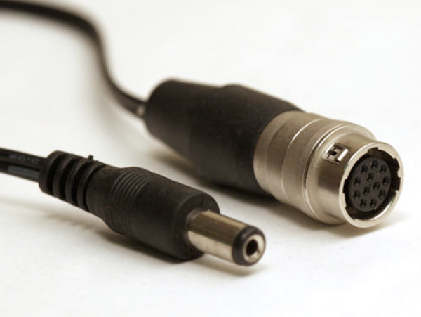
DC adapter cables for 12-pin lenses are readily available online.
These ENG lenses are designed to mount onto broadcast camcorders that, for more than a decade, have standardized both the lens mount (B4), and the jack for the lens cable connection to the camera. It's a standard 12-pin cable that carries power, record start and stop, iris motor control from the camera, and a toggle for the camera to show the return video feed in the viewfinder. Newer lenses augment these basic features with some new ones, but the features I describe are common to most ENG lenses.
I'll admit that I was not the first to "discover" any of this. In reality, I had planned on doing it for some time before I even acquired my DSLR. But searching the web, I found one article talking about providing power to the brown and green wires. Another article talks about the doubler. A third article shows the specialized lens adapter for use on Panasonic's AF100 ... the list goes on. All these various bits are hard to come by on their own, and incomplete. I took the pieces I found on the internet as a starting point and I put it all together. I made it work. Here's how you can do it.
The Lens Cable
The key to powering the lens is the lens cable. I've seen videos where end users hacked off the connector to get to the wires. At that point, you're guessing because there's no standard that says that this color wire or that color wire has to be the power for the zoom. The zooms can use whatever color wires they want. The standard is for the plug and the jack so the lens can connect with most any camera.
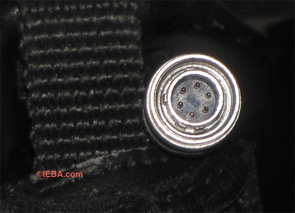
My 6-pin lens plug uses an old standard, but information is available.
For my first test lens, I chose an older, less expensive lens. I ended up with a 6-pin connector that mated to a Sony M3 tube camera that was used in the 1980s. I asked the seller of the lens to send me the jack from the camera and he included it since the camera was a "parts" machine anyway. Now, with all those pins, how do you know what pin does what? Well, I did what any connected gearhead would do. I called a Sony rep and asked for a schematic for the lens jack on the M3. If the lens you want was on an Ikegami, a Panasonic, or JVC camera, you can contact their respective professional divisions for more info.
Not knowing how fast I would get a response, I also put sent out an email to my fellow video professionals on the VidProTalk yahoo group. One member who works for a state TV agency went into the agency's old file cabinets in the basement and dug out the now-30-year-old manual. He took a picture of the schematic presented in the manual and e-mailed it to me. I had that in my hand just hours after I asked. (Thanks, Mark!) This information turned out to be critical, but confusing. Note how pin #1, travels on wire #9, and is coded as #4.
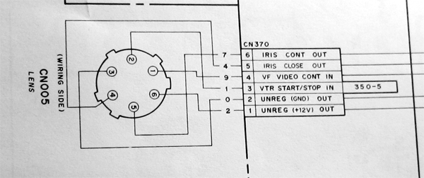
One schematic for the M3's lens jack.
Sony emailed me the very next day with another, different schematic. Here the pin numbers were corroborated and clear. I could ignore the other numbers in the schematic above. I find that it is always better to have more information than less. I this case, it can also be confusing that both the +12v and ground are both called "out" and there is no "in." Or, that looking at the Sony page below, +12v is listed in two places, and you need to understand that "ground" means the negative lead for the +12v you supply to the lens.
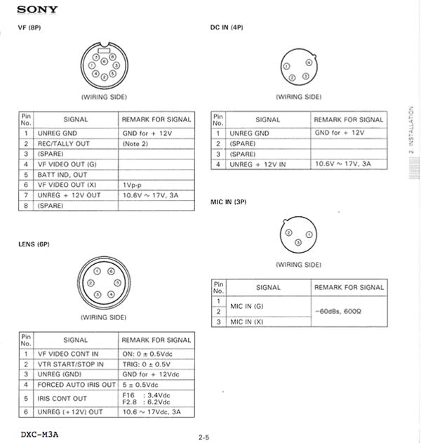
Sony's schematic from Sony for the M3's jacks.
Related Articles
DSLRs have become the standard by which current and future large-sensor camcorders are judged. But as we adopted DSLRs and primes to produce more "filmic" video for our clients, we left something critical behind: the feathery smooth servo zoom that serves feature film producers so well. So how do you get that capability on your DSLR?